
Model A & AA
Ford Garage
Transmission Shift Lever, Spring, & Retainer
Removal & Installation Tool

 fordgarage.com
There is little doubt that the two most dangerous jobs on a Model A Ford are removing and installing the transmission gear shift lever spring in the three speed transmission, and also the removal and installation of the rear axle suspension spring!
Both of those springs contain a tremendous amount of stored energy which can quickly, easily, and seriously injure you!
The whole point of this tool is to lessen the danger present when working with the compressed spring. Approach the task with safety and common sense foremost in your mind. Remove all onlookers and distractions from the work area. Wear eye protection and a full face shield and supple leather gloves.
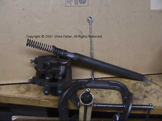
The following is a series of pics of a Model A Ford shift lever spring removal tool I made in 1991, based on the design and description given by a fellow I met in Indiana. He claimed that this is the type of tool that Ford originally used. I don't know about that, but it works great and it is the safest tool I've ever seen or used!
I've made the Bill Kenz spring compressor tool years ago, and I've done the wooden dowel and steel wire trick before, too, and I wouldn't ever consider doing those again on a bet.
This is the safest, fastest, and easiest to use shift lever spring removal and installation tool design I know of!
The tube diameter allows the spring, retainer clip, and shift lever to be removed and re-installed in the shift tower without removing the shifter forks or rails.
Another great feature is that the shift rails and forks can be removed more easily later if desired, after the shift lever and spring are out of the way!
Disassembly Procedure:
 fordgarage.com
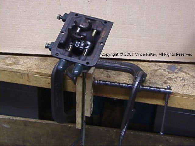
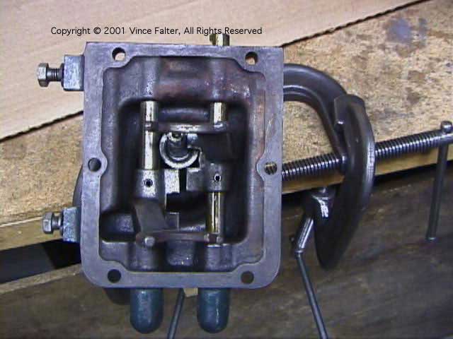
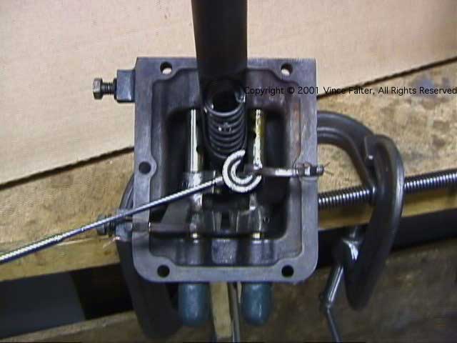
First, the shift tower lever is securely clamped to the bench top (or a low-mounted vise) in the preferred neutral beginning position for spring (and retainer clip) removal or installation, as shown above.
The plated lever is clamped with wood to protect the finish and grip the lever. Rubber-faced boards (like ping-pong paddles) would also work well for gripping and protecting the lever.
This allows the tool to be manipulated over the lever, and to be able to extract or insert the retainer while the forks and shafts are still installed in place in the tower.
 fordgarage.com
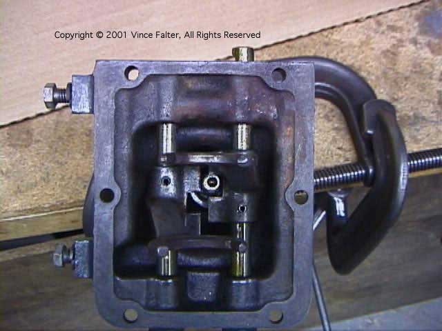
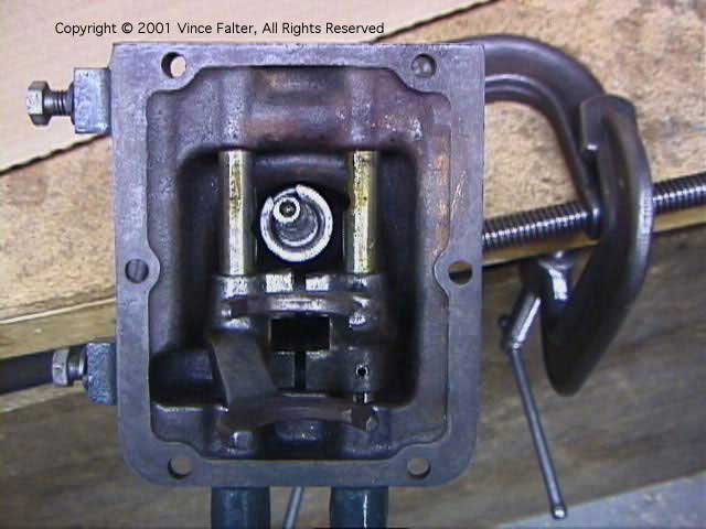
Next, move the driver side (LHD) fork (on right in pic above) with the lever ball to the 3rd gear detent as shown above.
 fordgarage.com
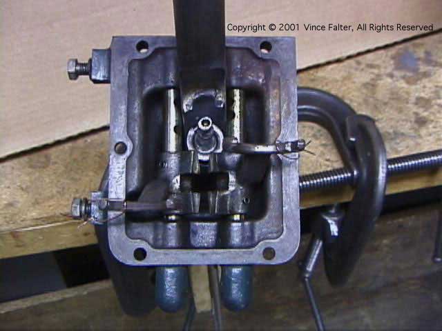
With the lever ball engaged in the driver side (LHD) fork, push the passenger side fork (on left in pic) to the vehicle rear (bottom in pic), and past the reverse gear detent. Then release the ball from the driver side fork.
 fordgarage.com
Next move the driver side (LHD) fork to the vehicle rear, and past the 2nd gear detent as shown above.
The lever is now disengaged from both forks, and both forks are completely out of the way for inserting the spring compressor tool.
Note the orientation of the open end of the retainer clip in the pic above. This is a preferred orientation for subsequent clip removal.
 fordgarage.com
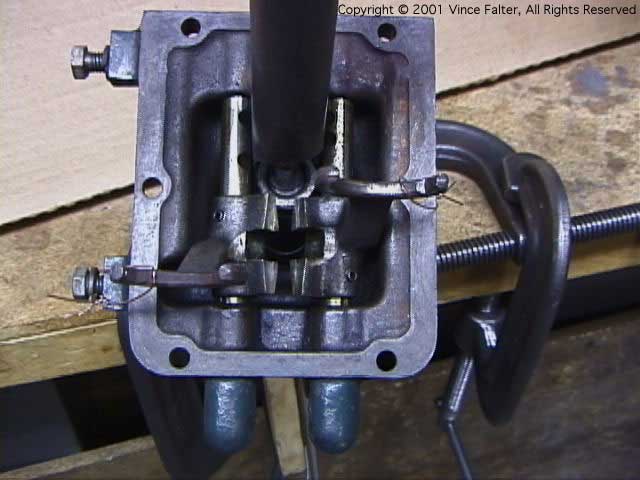
At this point, I like to wire the forks 'up and out', as shown above, to provide a little more space for inserting the tool over the spring.
The 'C' washer of the tool must be swung 'in' to engage the coil just beyond the retainer. The loop at the bottom of the tube bears against the spring and gives you some added leverage to force the 'C' washer between the two coils closest to the retainer.
 fordgarage.com
In the pic above, the tool is shown engaged in the first spring coil under the retainer.
 fordgarage.com
Now push down on the tool, and use a magnet stick to remove the retainer. The tool can also be used to rotate the spring and retainer around so the retainer will be aligned to come out the window in the tube.
 fordgarage.com
Voila! It is apart in less than 10 seconds after inserting the tool. (longer when taking pics!)
Just reverse this procedure to re-assemble!
Construction Details:
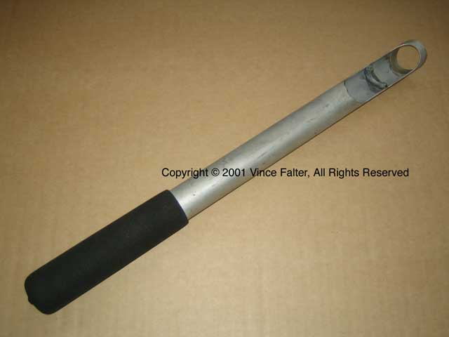
The tubing size is 1-1/4" OD x 0.065" wall 1026 (or 4140) DOM seamless steel tube. A tube length of 18-20 inches is suitable.The tube has a window cut into it allowing it to load over/onto the lever, spring, and the keeper at an angle, and can then be pulled into collinear alignment with the spring.
A 'C' washer made from a hardened steel washer is silver soldered (or TIG welded) into the upper half of the window in the tube, and at an angle to match the compressed spring helix.
This tool securely captures the spring top and bottom when compressed. As the spring is compressed, the tube covers the exposed end of the shift lever, preventing any possibility of the spring jumping out the window.
Even if the 'C' washer were to break free from inside the tube, the only place the spring can go is within the inside of the tube. It cannot escape the tube!
By clamping the lever securely, you can operate the tool with one hand and your body weight. I've since added a foam grip handle on it for added grip/control.
More related information on Ford Garage:
- For more Model A & B related information, use the Site Search box at the top or bottom of this page.
- Model A 1928 Gear Shift Lever and Tower Assembly
- Model A Transmission Shift Lever Differences
- Model A Shift Lever Butler Finish Details
- Model A Ruckstell Dual High Transmission
- Model A & B Gear Shift Lever Ball Variations
- Model A & B 1932 Los Angeles Olympics Shift Lever Ball
- Model A Mitchell Synchronized Transmission
Vince Falter
February 2001
