Model A & B
Ford Garage
Valve Tappet / Push Rod Adjustment
Rule of Nine


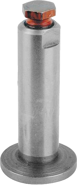
Described below is a timesaving method for adjusting or checking the adjustable valve tappet clearances when the engine is in the car and must be hand cranked. Original Ford valve tappets (push rods in Ford nomenclature) were solid and non-adjustable, but all modern replacements are adjustable.
The tappets (push rods as Ford called them) must have their clearances measured when they are on the heel of the camshaft lobe (lowest point).
The tappet clearances must be adjusted, set, and secured with thin wrenches when they are on the peak of the cam lobe. Hand crank the engine a few times and watch the valve stems and you will see this relationship.
The clearances cannot be adjusted or secured in the same operation or position as when the clearances are measured.
The Issue:
Ideally, the gap would be adjusted when the valve tappet was on the heel of the cam lobe while simultaneously measuring the gap with a feeler gauge.
Though the clearance gap can be measured while the tappet is on the lobe heel, the tappet adjustment is not accessible by wrench while on the lobe heel position. The camshaft must be rotated and the tappet raised in order to make an adjustment to the gap.
Conversely, the tappet can be adjusted while on the lobe peak, but the gap cannot be measured at that position. Thus a lot of cranking is typically required, alternating between measuring and adjusting.
Here's the Trick:
First of all, it is not necessary to know where the pistons are positioned.
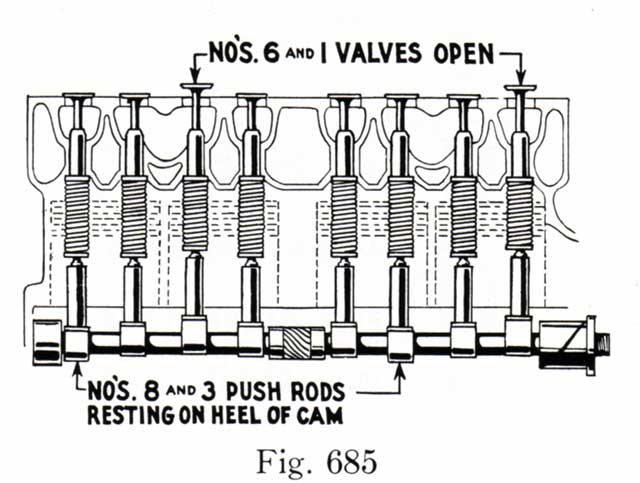
Valves are numbered 1 through 8, from front to back. Regardless of which valve tappet is on a cam lobe peak (and can be adjusted) at a given instance, there is another corresponding valve tappet that is on its lobe's heel (and whose gap can be measured).
By understanding the relationship between each of the valves, (Rule of Nine), you can do two things at once and adjust and measure multiple valves in a steady progression (if you keep track of your actions). This will greatly minimize the amount of time spent cranking, measuring, and adjusting.


The Rule of Nine relationship works like this:
If for instance the #6 valve is full open, then it can be adjusted with wrenches. Also at the same time the #3 valve tappet ("9" minus "6" equals "3") is on the heel of its cam lobe and its gap can be measured at the same time as #6 is being adjusted.
Now crank a little more until a different valve is full up and adjust it, and/or measure the gap on the other valve tappet whose sum equals "9" (e.g. if #2 is full up, then #7 can be measured, and #2 could also be adjusted if you know how much). Keep cranking until a different valve is up, and adjust it and measure the gap of the one whose sum equals "9".
Adjustable self-locking valve tappets use a 24 TPI bolt, which equates to a pitch in inches of 0.042" (one revolution of the bolt changes the gap 0.042").
Because the bolt head has six wrench faces, it is fairly easy to estimate rotating the bolt 1/6 of a revolution, which equals one wrench face, which equates to a 0.007" change axially at the gap.
Furthermore, with a little eyeball engineering, you can guesstimate 1/3rd of a rev of a hex wrench face with the two wrenches in your hand. This is ~0.002" of valve gap adjustment per 1/3 wrench face rotation.
With a little practice, you can measure and record the gap when the valve tappet is on its cam lobe heel, and can adjust it to within 0.002" of where you want it the very first time that same valve tappet is on its cam lobe peak (and is accessible by wrenches).
This can really minimize the amount of hand cranking necessary when the engine is in the car. If the engine is on a stand, then perhaps a lot of cranking is not such a big deal.
This procedure works very well on Model A camshafts, and quite well on Model B cams, though Model B camshafts have a slightly different lobe separation angle and the 'down valve' is not as centered on the heel when the corresponding "Rule of Nine" valve is at its peak.
Recommended Valve Tappet Clearances:
| Manufacturer's Recommended Tappet Clearance (inches) | ||
| Camshaft Design |
Intake Valve Clearance (gap) |
Exhaust Valve Clearance (gap) |
| Model A A-6250 |
0.015 | 0.015 |
| Model B B-6250 |
0.015 | 0.022 |
| Model BF BF-6250 |
0.015 | 0.017 |
| Stipe IB330 |
0.012 | 0.012 |
| Stipe IB340 |
0.012 | 0.012 |
| Stipe RR340 |
0.012 | 0.014 |
| Stipe HP350 |
0.010 | 0.010 |
The table above shows the manufacturer's recommended (cold) gap valve tappet clearances for several cam profiles.
A typical clearance setting of 0.013" intake and 0.015" exhaust is also commonly used by many people, and is also used when the cam profile or the cam grinder's recommendation is unknown.
It is best to avoid setting the exhaust valve gap too small, as this can create insufficient heat transfer time for the valve on the seat, and can ultimately burn the exhaust valve.
The linear thermal expansion of a hot exhaust valve also has the effect of increasing its length more (and further decreasing the clearance gap), compared to the lesser expansion in length of a cooler intake valve.
When in doubt, err on the side of setting the exhaust valve gap larger, rather than smaller.
More related information on Ford Garage:
- For more Model A & B related information, use the Site Search box at the top or bottom of this page.
- Model A & B Valve Push Rod Discussion
- Model A & B Original Ford Camshaft Details
- Model A & B Bill Stipe Camshaft Specifications
- Model A & B Camshaft Timing Gear Varieties
- Model A & B Camshaft to Crankshaft Gear Alignment
- Model A & B Camshaft to Crankshaft Positioning
- Model A & B KR Wilson BV-45 Step Feeler Gauge
Vince Falter
September 2000

