
Model A & B
Ford Garage
Brumfield Cylinder Head Gasket Installation Instructions

 fordgarage.com
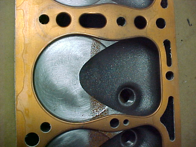
Brumfield 5.9 Cylinder Head and Fel-Pro 7013 Gasket
In many postings on internet message boards, Larry Brumfield has shared a lot of his knowledge about engine operation, combustion, intake and exhaust theory, and cylinder head design, construction, and manufacture.
His cylinder heads were produced and sold for many years with nearly all customers reporting great satisfaction and trouble-free service.
Many thanks to Larry for providing the head and gasket instructions below, and allowing it to be presented on Ford Garage!
These instructions are detailed and lengthy for good reason!
READ THEM!
Here are Larry's latest instructions on the proper head gasket procedures for his cylinder heads in his own words:
Head Nut Torquing Instructions:
Follow these instructions and please ignore any instructions to the contrary put forth by any self-appointed experts blowing their mouths on various Model A message boards and elsewhere, who think they know best for all Brumfield Head users, especially on the torque values and re-torque procedure.
Lesser torque amounts have proved unreliable with blocks that were out of flat a little more than I like to see. I have good reason for every part of these instructions:
-
Make sure the block is not off more than 0.002 of an inch in flatness as measured in the center with a machinist straight-edge that spans the length of the block's gasket area, and use accurate feeler gauges with good edges. This method of inspection is not as accurate as can be done with a machinist’s surface plate but is sufficient to reliably detect problematic out-of-flat on most blocks.
-
Make sure the head is not off more than 0.002 of an inch (preferably less) in flatness as measured in the center in the same manner as with the block. This method of inspection is not as accurate as can be done with a machinist’s surface plate but is sufficient to reliably detect problematic out-of-flat on most heads.
If the head is out-of-flat more than 0.002 of an inch, then have it resurfaced and make sure the surface finish made by the machine is between RMS 90-110, which is just rough enough to slightly feel with your fingernail.
You don't want a mirror smooth finish on a flat head, nor do you want too rough a texture either. A slight texture on a flat head tends to grip the gasket and that's what you need.
-
On a Brumfield Head, use a new copper-clad Fel-Pro 7013 C (R2 or R3 or R4) head gasket and NO OTHER. We install them with a light coating of chassis grease smeared across them and that's all.
However, you can use spray sealer if you like; copper coat spray by Permatex for example, BUT apply just enough to cover on both sides with no runs and that's it; and install the gasket and head while the coating is STILL STICKY, very important. If you let the sealer dry and then install the gasket, it can cause leaks.
-
Check the condition of the studs and nuts. You need studs and nuts that have good threads and a high enough grade strength to accurately hold a final torque amount a little greater than Ford’s original, as applied with an accurate torque wrench. Grade 8 studs and nuts will hold the torque value the best.
The correct way to install the studs is just finger tight. Do Not Tighten. If tightened, the stud can cock over at an angle as it will tend to seat on the runout of the thread.
Some people prefer to back the stud out a 1/4 turn or so but the studs will typically run back in that 1/4 turn when the nut gets tightened. Screwed all the way in finger tight utilizes the maximum amount of available threads in these old blocks and provides the correct length above the block for the stud to be correctly above the head to accept the nut and protrude a couple threads above it, assuming of course that the studs, nuts and the head are made to original Ford specifications.
Using a light, check the condition of the threads in the block’s stud holes. If the stud hole threads are badly worn or damaged, then correct them with the proper inserts.
Using a light, examine the sides and the bottom or base of the stud holes. If any have rust pinholes or are broken off, thus exposing the stud hole to the water jacket, oat the stud’s threads with a light coating of high-temp RTV silicone and allow a tiny bead of it to form around the base of the stud when it’s screwed all the way in. Allow the RTV to dry overnight after the studs are installed.
-
Make sure the stud bosses where the nuts make contact are free of paint and are smooth clean metal. Apply a drop of motor oil to each boss so the bottom of the nut can slide on it. Lube the stud and nut threads with motor oil. It’s also a good idea to apply some anti-seize lubricant to the coarse end threads of the studs if not using high-temp RTV. Also, since there is sufficient clearance between the studs and the stud holes in the head, the following is not critical, but If desired, it’s OK to lightly grease the sides of the studs with anti-seize lubricant but do not allow it to get on the fine thread or nut end of the studs.
-
Torque in sequence following the pattern below. Start with finger tight on each, then say 20 pounds or so on each, then 40, then a final amount of 60 pounds on a Regular Brumfield head 5.9 and 65 on any Brumfield Super Head at 6.5 to 1 or greater compression ratio.
As referenced above, the torque values recommended are the most reliable for Brumfield Heads; even more if the block gasket surface is out of flat a little more than I like to see. Moreover, any stud hole that won’t stand 5 pounds of extra torque on the nut, over the standard, stock 55 pounds, has poor threads indeed. In addition, 65 pounds of torque on Brumfield Super Heads, 6.5 to 1 ratio and greater, is no doubt an increase over stock but blocks in good shape will stand 65 pounds and more and will not pull out or distort.
And while it is true that all Model A block threads are old and many are not in good shape, the reason for failure typically lies in the mechanic or installer not knowing how to check if the holes will take the required torque. This can be determined easily with a simple test using a short, grade 8 stud, a flat spacer 2" in diameter to spread the load, 3/4" thick with a 15/32" hole bored in the center, and a hard, high nut. All edges on the spacer should be chamfered and the block surface should be clean. The stud and nut threads should be lubed with motor oil. Put the spacer over the hole , screw the short stud all the way in finger tight, put on the hard, high nut and torque to the required torque amount. If any block threads pull or distort you cannot screw the test stud out by hand, thus revealing the hole needed a proper insert before the test if at least original Ford strength was or is desired.
Model A race engines requiring high torque amounts are often inserted with steel inserts, using a pipe thread, whose diameter allows the insert’s external threads to extend beyond the depth of Heli-Coils into the wall of the stud hole, and also the top edge of the hole is chamfered but only as a minor precaution. They can stand up to 100 pounds of torque and do not pull out! However, that type of insert notwithstanding, it’s proof that a Model A deck in good condition is not as fragile as some people portray them to be, including a few message board characters as well as a few engine rebuilders.
The bottom line is if the threads in the stud holes will not stand the required torque due to being fatigued from age, worn, worn out, stripped or rotted then replace them with proper inserts into solid metal so correct and faultless torque amounts can be utilized and maintained whether the head is stock or higher compression.
-
Do not use a gasket beneath the water neck. Make sure the neck is flat (if it's not then have it machined flat) and use a light smear of RTV silicone instead of a gasket.
-
Complete the 4 step re-torque process below, A through D.
Then read the detailed explanation for backing the nuts off in the next section lower on this page:-
After the head has been installed and torqued in proper sequence to the final torque amount, and all components to make the engine run have been installed (not to forget oil and water), start the engine and let it run until it reaches sufficient operating temperature, at least 15 minutes or so.
Do not run the engine without water during the re-torque procedure or EVER for that matter! There are some misguided A’ers and a few engine builders who think that running the engine for a couple minutes without coolant or water will somehow cause the head and gasket to settle in better, or some such nonsense.
Personally, I’m not in favor of running an engine without water in it for any amount of time. All the iron has to do is get hot enough for the oil to cook off the upper cylinder walls. Who can tell us with any accuracy exactly how long that takes and back it up with proof?
With no water on the other side to absorb the combustion heat, that iron gets hot quickly. When the oil film cooks away, then things get REAL hot! In no time at all the rings, pistons, and the cylinder walls can gall to one degree or another and even allow possible metal migration.
Metal migration is when 2 parts come together with enough force or lack of lubrication to heat and cause metal from one to transfer to the other. It is a form of fusion welding. The piston’s aluminum being softer and has a lower melting point usually goes first. Once aluminum gets on the walls, it gets rough and tears up the rings.
Turn the ignition off and allow the engine to cool a few minutes but not completely cooled off. Then, starting at nut #1, re-torque in proper sequence to the final torque amount on all the nuts.
Re-torquing without the engine cooled off, i.e., warm threads, is not the best for accuracy. But when the engine is run the first time after installing the head, sometimes the nuts get loose enough to allow the gasket to seep if the engine is allowed to cool off completely before re-torquing. Sometimes the nuts will be surprisingly loose.
-
Next, start the engine and drive the car at a slow speed around the block or down the street and back, about a mile or a mile and a half or so at most. Turn off the ignition and allow the engine to cool off completely.
Then, starting at nut #1, re-torque in proper sequence to the final torque amount on all the nuts. But before re-torquing any individual nut, back it off 1/8 of a turn, and then torque immediately to the final torque amount. Do this on all the nuts one at a time in proper sequence. Do not loosen them all at once.
-
Next, start the engine and drive the car at a little faster speed for a good drive of say 7 or 8 miles or so. Turn off the ignition and allow the engine to cool off completely.
Then, starting at nut #1, re-torque in proper sequence to the final torque amount on all the nuts. But before re-torquing any individual nut, back it off 1/8 of a turn, and then torque immediately to the final torque amount. Do this on all the nuts one at a time in proper sequence. Do not loosen them all at once.
-
Usually 3 re-torques are enough. You’ll know when you are done because the nuts will re-torque to the same position at full torque that they were when torqued on the previous re-torque.
However, even after enough re-torques appear to have been performed, it is good practice to re-torque one more time after running the engine about 500 miles or so as it is possible the gasket may have compressed a little farther.
With the engine completely cooled off, starting at nut #1, re-torque in proper sequence to the final torque amount on all the nuts. But before re-torquing any individual nut, back it off 1/8 of a turn, and then torque immediately to the final torque amount. Do this on all the nuts one at a time in proper sequence.
Do not loosen them all at once.
-
Remember!… Always allow the engine to be completely cooled off before all subsequent re-torques are performed and use the above back-off method to perform them. Do this regardless of the head being stock or otherwise as it is by far the most accurate method to ensure even clamp from nut to nut and the avoidance of seeps and premature gasket failure on the Model A Ford.
Here's the head nut torque sequence diagram:
⑬ .... ⑦ .... ① .... ⑧ .... ⑭
⑪ ... ⑤ .... ② .... ④ ... ⑩
Larry Brumfield
May 2016
Loosening Nuts Before Re-torquing:
A few words concerning the purpose of loosening each nut 1/8th turn, which some Model A’ers don’t understand or find odd:
When a flathead is installed and the nuts are tightened, the gasket, being a yieldable material, is being compressed between the block and the head. Next, when the engine is cranked and running, the compression and combustion tries to drive the head off. The head pushes against the nuts, the nuts resist and the gasket yields and further compresses. Tension is then taken off the nuts. Then the nuts are re-torqued once again to tighten the head against the gasket and block.
The whole process is repeated when the engine is run again and must be repeated as many times as are necessary until the gasket compresses as far as it’s going to compress and the nuts stay tight at the final torque amount. Three re-torques are usually enough but one final re-torque after about 500 miles and a few runs at higher speed and at heavier loads is good practice, as there might be a little further compression of the gasket.
When re-torquing, it is usually not normal practice to back off nuts or bolts. However, on a Ford flathead, some of the cylinder head nuts can develop an increase or higher static friction as compared to the static friction of some of the other cylinder head nuts or a resistance to movement after they have been previously tightened or torqued. Or in other words, once tightened they sometimes tend to stick and the amount of torque required to get the nut to move is a little greater than the torque value that was intended to be applied.
When the torque is applied by the torque wrench in the standard way, the force must be great enough to break the nut free and move tighter. In the process, some of the torque is wasted overcoming the higher friction and the wrench may not apply the correct torque amount as set or viewed on the wrench. The result is the applied torque can be incorrect. And, if the increase in static friction is high enough, the nut may not break free at all at the torque amount set on the wrench.
In other words, the installer can be fooled into thinking that the nut is at the value set on the wrench whereas if the nut was not sticking it would turn tighter, as it should when the gasket has not completed its compression process. This possible sticking of the nuts can happen to a degree even with lubed threads after a little time goes by and a few hot/cold cycles. Talk about possible uneven clamp from nut to nut, leaky gaskets and premature gasket failure!! …. Anybody ought to be able to understand it.
If it could be guaranteed that the nuts would never stick, then backing them off would be unnecessary. However, to avoid the problem and to assure accurate re-torques and and even clamp from nut to nut, the nuts should be backed off, or cracked back slightly before being re-torqued and then retightened or re-torqued immediately.
Backing each nut off 1/8 turn does not loosen them in the true meaning of the word, loose. The procedure merely moves the nut only 45 degrees of rotation and just enough to overcome the stick that may or may not have occurred between the nut and stud threads and including the stud boss and nut face.
Since the torque readings are dependent upon the coefficients of friction present under the nut face and in the threads, there must be a smooth, uninterrupted rotation to have accuracy when the re-torque is applied. And last but not least, nuts have been observed that appeared to be tight at the final torque amount, when re-torqued and NOT backed off, only to turn as much as 2/3 to nearly a full turn farther when backed off and re-torqued at the same torque amount!
Apart from gasket surfaces being too far out of flat, insufficient final torque amounts, worn or low strength studs and nuts, etc.; many a leaking or seeping gasket and many a premature gasket failure on Model A’s are caused by the uneven clamp that is possible from nut to nut due to improper re-torques.
Larry Brumfield
July 2016
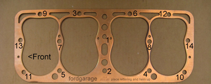
Note: The gasket shown in the illustration above is a Model B gasket, not a Fel-Pro 7013
More related information on Ford Garage:
- For more Model A & B related information, use the Site Search box at the top or bottom of this page.
- Model A & B Cylinder Head Flatness Requirements by Larry Brumfield
- Model A & B Brumfield 5.9 Cylinder Head & Head Gaskets
- Model A & B Snap-on Cylinder Head Nut Wrench proper torque application tool
- Model A & B Cylinder Head and Distributor Pullers by Ron Cloat
- Model A & B Broken Cylinder Head Stud and Bolt Removal
- Model A & B Cylinder Head Stud Removal Tools
- Model A & B Cylinder Head Gasket Guide comprehensive listing
- Model A & B Cylinder Head Compression Ratios
- Model A & B Cylinder Head Nut Tightening Sequence
- Model A & B 7/8-18 inch Spark Plug Heat Ranges by Larry Brumfield
